The ALIS Spider is known for being unusable with an AC adapter. This is due to the fact that this entry is not filtered at all: the noise produced by the AC adapter creates a loud noise.
This little PCB pretends to fix that issue. It take as input any commonly available 12V DC adapter and produces a regulated output of 8V DC on 9V battery snap-on contacts. It has roughly the size of a 9V battery and can be inserted in the battery door of the ALIS Spider.
It can be used wherever you want to substitute a 9V battery by an AC adapter.
Usage
Characteristics of the AC adapter:
- output 12V DC
- hollow plug 5.5 / 2.1 mm
- positive pin inside

Those are some of the most common ones.
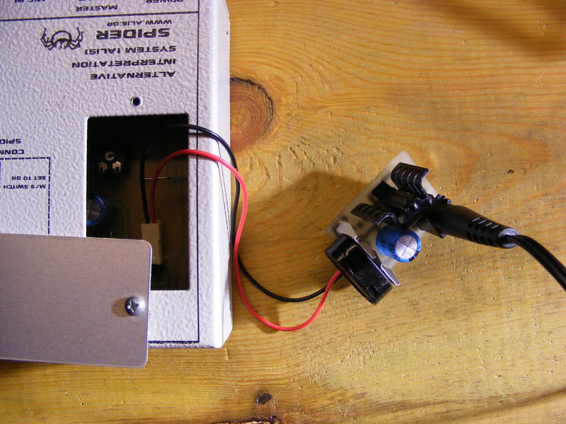
Plug the adapter into the plug going through the plastic protection on top of the regulator.
Plug the battery connector of the Spider on the battery snaps on the side of the regulator.
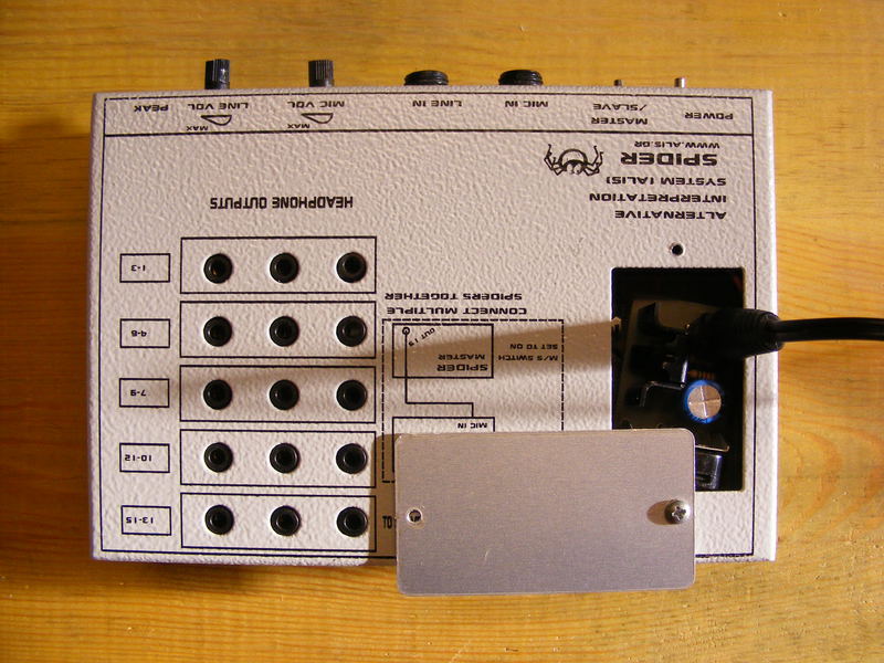
Photos
On these photos the regulator has no plastic protection.
Eagle files
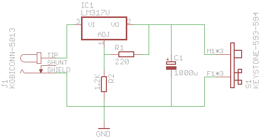
Schematics
Part list
Name   Value              Package                   #   Mouser reference
----   -----              -------                   -   ----------------

C1     1000uF             ER-10,5                   1   140-REA102M1ABK1012P
IC1    LM317              TO220V                    1   511-LM317T
       Heat sink          Aavid Thermalloy 6237BG   1   532-6237B
J1     Power plug         Kobiconn 5013 [1]         1   163-5013
R1     220                0207/7                    1   291-220-RC
R2     1.2K               0207/7                    1   291-1.2K-RC
S1     Battery contacts   Keystone 593-594 [2]      1   534-593 & 534-594
       Heat shrink tube   1.5"                      1   650-TAT125112
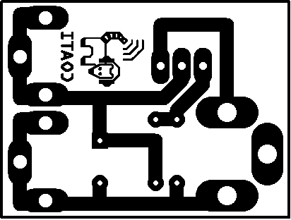
Board
Building instructions
Drills
- ø 0.8 for C1, R1, and R2
- ø 1.7 for IC1, and S1
- ø 2.5 for J1
Notes
- Suggested mounting order: R1, R2, C1, J1, S1, IC1.
- J1: Cut the wider parts of the leads to 2.5 mm.
- IC1: mount all the way through the drills so that the case almost touches the PCB.
- Once mounted, wrap the circuit in a 1.5" heat shrink tube of 4 cm long.
Troubleshooting
- If the output voltage is around 10 V, you probably have a false contact between the pins 1 and 2 of IC1.
- If the output voltage is around 7 V, you probably have inversed the pins of the L317.
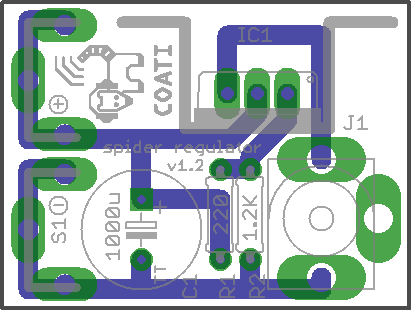
PCB layout