Introduction
Make sure you read our assembly tips.
The components marked with a + have a polarity.
To mount them the right way, look for hints either:
- on the screenprinting on the PCB itself
- in the Eagle file of the board
- in the datasheet of the component linked from the parts list
PCB drill sizes
- ø 0.8: todos los agujeros al no ser que sea especificado de otra manera.
- ø 1.0: patas de los potenciómetros P1 y P2, conector de la batería X1 y diodo D1.
- ø 1.2: patas del LM317 U1 e interruptores S1, S2 y S3.
- ø 1.5: patas de los jacks de entrada J2 y J3, pata central de los enchufes de auriculares H1 hasta H14.
- ø 2.0: fijaciones de plástico de los jacks de entrada J2 y J3.
- ø 2.5: patas pequeñas del enchufe de alimentación J1, fijaciones de los potenciómetros P1 y P2, patas laterales de los enchufes de auriculares H1 hasta H14 y patas del enchufe de extensión J4.
- ø 3.0: pata grande del enchufe de alimentación J1 y separadores.
Preparation
Solder the 5 DIL8 sockets+. The socket pins which have to be soldered on top have a longer shape to ease soldering.
Mount the spacers: the spacer itself goes on the bottom of the PCB, the washer, and then the bolt go on top of the PCB.
Comprobar que no hayan corto-circuitos entre las patas de los zócalos.
Power supply
Soldar J1 a la vez por arriba y por abajo de la PCB para hacerle más fuerte.
Plug the heat sink on the LM317 U1: the flat part of the heat sink touches the metal plate of the LM317. Mount the LM317 on the bottom of the PCB, and bend the wider part of the LM317 leads to fit the heat sink in its correct position: the flat part of the heat sink touches the bottom of the PCB. Solder U1. Beware: it is all-right for the heat sink to touch the central lead of the LM317 but not the other ones. Then separate a bit the LM317 from the PCB to make sure it doesn't touch the other components.
Solder J1, U1+, R5, R38, C19+, X1+, S1, and R16. C19+ must be well pressed onto the PCB.
- Make sure that S1 is well pressed onto the PCB on all its sides.
Solder LED1+ so its base is 11 mm above the PCB. The flat side of the LED must be on the side of the switch.
Solder D1+. The white marker on the diode must be the side of the switch.
Enchufar el transformador de 12 V y mesurar 8 V entre la pata lateral de J1 (GND) y la pata central del LM317 (VCC).
Desenchufar el transformador y conectar la batería de 9 V. Comprobar que la LED se encienda con la batería solamente.
Virtual ground
Solder R14, R15, C14+, and C15.
Mount IC2+.
Mesurar 8 V entre la pata 8 de IC2 (VCC) y GND.
Mesurar 4 V entre la pata 5 de IC2 (VCC/2) y GND.
Mesurar 4 V entre la pata 6 de IC2 (VCC/2) y GND.
Floor line amplification
Solder J3, S3, R40, C20+, R37, R30, C21, and C23+.
Mount IC4+.
Con un osciloscopio, visualizar una señal de linea en la pata 1 de IC4.
Para alimentar la entrada de linea con un señal seno de manera continua, se puede ejecutar el comando siguiente en Linux:
speaker-test -t sine
Floor power amplifier
Solder P2, C9, C26, R36, C27+, R11, C11+, R31, R35, H13, and H14.
- Make sure that P2, H12, and H14 are well pressed onto the PCB on all their sides.
Mount IC5+.
R11 determina la ganancia del LM386. Como explicado en la hoja de datos, sin esta resistencia, la ganancia es de 20, con una resistencia de 1.2 kΩ es de 50 y con un puente es de 200. Pongamos una resistencia de 1.2 kΩ por defecto.
- Escuchar una entrada de linea en los 2 enchufes de auriculares.
Floor microphone amplification
Solder R29, R32, C22+, C24, R34, C25+, and R33.
Escuchar una entrada de micrófono en los enchufes de auriculares.
Interpretation line amplification
Solder J2, S2, R1, C1+, R3, R4, C2, and C16+.
- Make sure that S2 is well pressed onto the PCB on all its sides.
Mount IC1+.
Con un osciloscopio, visualizar una señal de linea en la pata 1 de IC1.
Interpretation power amplifier
Solder R12, P1, C8, C3, R10, C7+, C10+, R9, C5+, R28, H12, R27, H11, R26, and H10. C10 and P1 must be well pressed onto the PCB.
- Make sure that P1, H10, H11, and H12 are well pressed onto the PCB on all their sides.
Mount IC3+.
R9 determina la ganancia del LM386. Como explicado en la hoja de datos, sin esta resistencia, la ganancia es de 20, con una resistencia de 1.2 kΩ es de 50 y con un puente es de 200. Pongamos una resistencia de 1.2 kΩ por defecto.
Soldar C10 por debajo de la PCB.
Escuchar una entrada de linea los 3 enchufes de auriculares.
Interpretation microphone amplification
Solder R2, C4+, R6, C6, R8, C12+, and R7.
Escuchar una entrada de micrófono en los enchufes de auriculares.
Interpretation headphone plugs
Solder R20, R21, R22, R23, R24, R25, R26, R27, R28, H4, H5, H6, H7, H8, and H9.
- Make sure that H4, H5, H6, H7, H8, and H9 are well pressed onto the PCB on all their sides.
Escuchar una entrada de micrófono en los 12 enchufes de auriculares.
Extension plug
Cut out the three plastic knobs of the RCA plug J4 (the two square ones and the round one) so that the main package touches the PCB.
Soldar J4.
Mesurar 8 V entre el punto caliente del enchufe RCA rojo y GND.
Con un osciloscopio, visualizar una señal de linea en el punto caliente del enchufe RCA negro.
Enclosure
Panel
Print the layers "Document (48)" and "Screenprint (102)" of the board design on the side of the enclosure which has the battery lid.
Taladrar todos los agujeros a ø 2 primero y luego a ø 5.
Taladrar los agujeros de los potenciómetros y enchufes de auriculares a ø 7.
Sides
Cerrar la caja con sus tornillos. Taladrar primero a ø 2 y luego a ø 5 para poder ajustar el posicionamiento:
- Enchufe de alimentación: ø 7. Centrar en la unión entre las dos partes de la caja.
- Jacks de entrada J2 y J3: ø 9. Centrar en la unión entre las dos partes de la caja.
- Enchufe de extensión J4: ø 10. Centrar a 1.0 mm encima de la unión entre las dos partes de la caja.
Battery lid
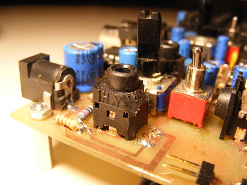
You will notice that the battery lid is sometimes hard to open when the enclosure is closed and screwed. To solve this problem, cut the upper right corner of H14 with a cutter, like shown on this picture: